Twenty-First Century Super Highway Constructed
with New Technology
Tokai Ohbu Viaduct and The Third Shimizu Tunnel in The New Tomei Expressway

A SUPER HIGHWAY
DESIGNED FOR MAXIMUM
SPEED LIMIT OF 140 km/hr.
Now, a quarter-century after the completion of the Tomei and Meishin Expressways, the construction of the New Tomei and Meishin Expressways is about to swing into full gear.
Since opening in 1969 the total number of vehicles to travel on the Tomei and Meishin expressways amounts to about 3 billion. As a road artery serving the Tokaido Megalopolis, the expressways have contributed much to Japan's economic growth and social development. However, urban traffic congestion resulting from an increase in traffic volume has caused the expressways to lose their capacity to provide smooth, speedy transit. Therefore, this new project was planned as a drastic measure to recover this capacity.
The new Tomei and Meishin Expressways were planned as national expressways under a comprehensive national land development plan. They have a total combined length of about 490 km, and consist of the New Tomei Expressway between Tokyo and Nagoya, with a total length of about 320 km, and the New Meishin Expressway between Nagoya and Kobe, with a total length of about 170 km. Of the expressway sections, the construction of three sections with a total length of about 303 km has already commenced. As a super highway in the 21st century, to assure safer and more comfortable high-speed transit, the six-lane highways are designed for maximum speeds of 140 km/hr. throughout the entire system, excluding urban sections, thus linking Tokyo with Kobe in about four hours. Classifying the entire expressway by type of road structure, bridge sections account for 40%, tunnels 20%, and earthworks 40%, bridges and tunnels making up a larger portion compared to existing expressways due to the mountainous nature of the new route.
Under a policy to develop and introduce new
technology, including rational design and construction, a variety of new
technological and construction methods are being employed for the efficient
execution of this project. Two typical examples of "new" construction, the Tokai
Ohbu Viaduct and Third Shimizu Tunnel, are introduced below.
SUB AND SUPER-
STRUCTURES OF THE TOKAI
OHBU VIADUCT
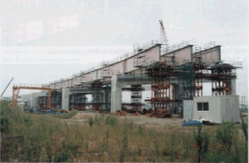
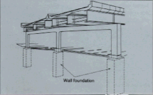
New technology and construction methods enhancing constructability and cost effectiveness were employed for this viaduct: wall type foundations were adopted for the substructure, and a reduced number of main steel girders for the superstructure(Photo 1). The wall foundation (a kind of cast-in-situ diaphragm wall with a standard cross section of 2.4 m in width, 3.0 m in length and 19.5 m in height) is an in-situ concrete foundation shaped like a single wall(Fig. 1). Since a utility tunnel runs beneath Route 302 under the expressway route and there was no space to install footings, the wall foundation, in lieu of RC piles, was constructed to directly support the moment-resisting viaduct. This is the second application of this type of viaduct in Japan. Since there are many private homes near the route and it is necessary for the expressway to cross national highways, prefectural roads, and railways, this construction method has shown advantages over conventional construction methods in terms of fewer construction processes, less noise and vibration, and less effect on surrounding environments.
To improve constructability and cost effectiveness, a study was made from an engineering viewpoint on the adoption of this structure. The bearing stratum, called the Tokai stratum, is an alternate soil layer consisting of a sandy layer and a hard clayey layer with N-value of 50 or more. The results of calculations done on the depth of embedment under the latest road design specifications showed a need to embed some foundations to a depth of 10 m or more into the bearing stratum. Therefore, a loading test was conducted for the wall foundations with test results reflecting on the design. As a consequence, the depth was decreased to a minimum of 2.4 m, leading to a substantial reduction in construction time and costs.
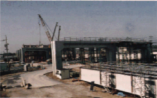
The superstructure consists of a 31 m-wide, six-lane road resting on three moment-resisting piers which are constructed on the wall foundations; so supporting girders would require large cross sectional areas if they were constructed with normal reinforced concrete. Therefore, a prestressed reinforced concrete (PRC) structure, that has the advantages of both prestressed and reinforced concrete, was adopted for the girders. This made it possible to reduce dead loads of the girders, reduce cross sectional areas, ensure road clearance limits, and improve exterior appearances (Photo 2). Furthermore, to save manpower, rationalize fabrication and construction work, and reduce construction costs, precast PC floor decks and a reduced number of main steel girders were adopted for the superstructure.
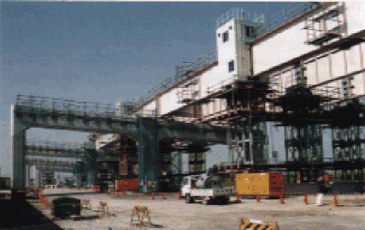
Generally speaking, 5 to 6 steel girders spaced
every 2.5 to 3.0 m are standard if viaducts are designed conventionally for a
three-lane divided expressway with a similar road width (about 16 m) to the New
Tomei Expressway. In contrast, three girders spaced roughly every 6 m is the
pattern for our viaduct. The spacing can be enlarged to about 10 m by
streamlining its structure as well as simplifying paired cross braces into
lateral ones. In addition, design, fabrication, transportation and erection have
been rationalized and outward appearances improved: for instance, field joints
are provided at places where the cross sections of main girders change; high
tension bolts are used for spliced joints between main and transverse girders;
and main girders are welded in the field (Photo 3). Furthermore, reaction
dispersion type rubber bearings are adopted to enhance earthquake resistance and
stability under traffic loads.
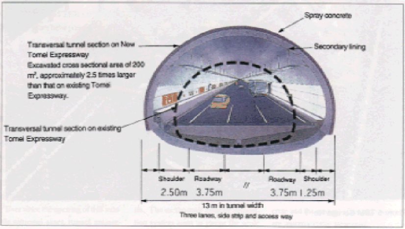 Fig.2 Transversal tunnel section
THIRD SHIMIZU TUNNEL
DRIVEN WITH GIANT TBM
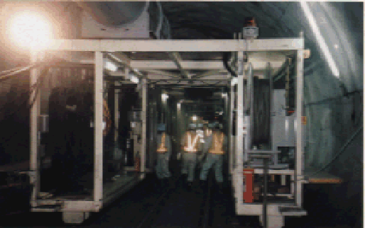
Tunneling work for the New Tomei Expressway was first started in Yoshiwara, Shimizu-city, in June 1996(Photo 4). As described earlier, tunnel sections account for 20% of the total projected length of about 303 km. Because these tunnels are to be 3 lanes wide, they have an excavated cross sectional area of about 200 m2, about 2.5 times larger than those on the existing Tomei and Meishin Expressways (Fig. 2).
By courtesy of Shizuoka and Nagoya Construction Bureaus, Japan Highway Public Corp.
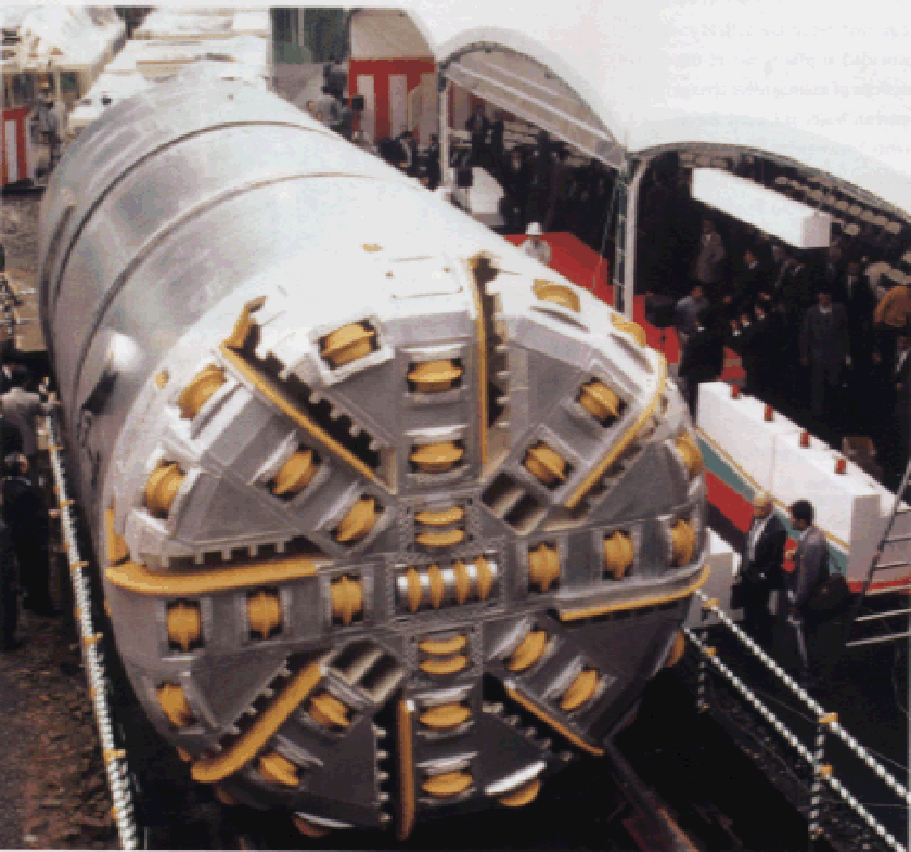
A tunnel boring machine (TBM), named Suruga No. 1,
is being used to bore these tunnels. (Photo 5) Since soil conditions, such as
the location of faults, are explored after a pilot tunnel is excavated by the
cylindrical, full-shield type TBM (5 m-dia. by 11.2 m long), the construction
methods best suited to the conditions encountered can be adopted when the tunnel
is enlarged during the next stage. That is, the tunnel can be reinforced in
advance in response to local conditions, or the amount of explosives increased
as required, thus allowing safe, quick and cost-effective tunneling.
Another feature of the TBM is that it can make a U-turn underground. The machine is constructed in three sections, with two knee sections, and equipped with eight thrust jacks. Because sufficient thrust can be obtained from only four jacks on one side, the machine can execute a 30 m radius U-turn. The machine is scheduled to make a U-turn and drill a pilot tunnel on up-lanes about 870 m from the west entrance after excavating a pilot tunnel on down-lanes. It tunnels at a maximum speed of 20 m a day and an average speed of 300 m a month.