The Soundness of the Longest Tunnel in the World

NINE YEARS AFTER OPENING
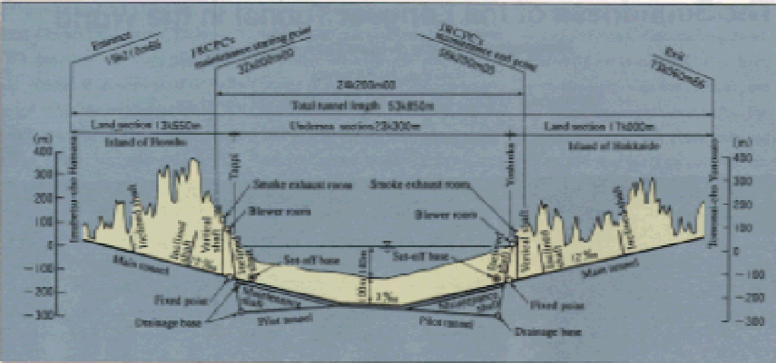
Nine years have passed since the March 1988 opening of the Seikan Undersea Tunnel, at 53.9 km, is the longest tunnel in the world. The massive public attention has died down and the tunnel now carries out its mission as a main artery connecting the islands of Honshu and Hokkaido, carrying a total of about 100 scheduled commuter and freight trains (on both inbound and outbound lines) daily for a yearly total of 2.1 million passengers and 5.8 million-tons of freight.
Ever since the opening of this valuable national
asset, tunnel maintenance has been carefully performed, particularly on undersea
sections. The present maintenance status of the undersea tunnel structure is
introduced below(Fig. 1).
TUNNEL MAINTENANCE
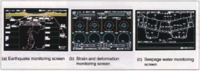
Tunnel maintenance consists of various monitoring, measurement and inspection systems: for instance, an earthquake disaster prevention system to ensure safe train operation in the event of earthquakes, measurement of displacements in tunnel cross sections, measurement of ground behavior, and chemical analysis. The earthquake disaster prevention system aims to gauge the scale of earthquakes as well as control train operations; UrEDAS (Urgent Earthquake Detection and Alarm System) is installed at four locations, and Modified NEWS (a modified-for-tunnel-use version of the New Earthquake Warning System used on Bullet Train Lines) is installed at six locations both inside and outside the tunnel. In the event of an earthquake, accelerations detected with these systems are displayed on monitors and at the same time an alarm is activated (Photo 2). Further, to monitor tunnel behavior during earthquakes, variations in strains on tunnel lining concrete and the amount of seepage water are automatically measured.
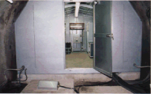
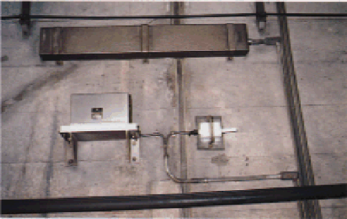
At each of four locations, selected from among tunnel sections which proved difficult during construction or where bad geological conditions were noted, strains at seven points in the longitudinal direction and at 14 points in the circumferential direction are measured automatically using high sensitivity strain gauges (Photo 3). Along the main tunnel, pilot tunnels and maintenance shafts, flow meters in drain gutters measure the seepage water flow rate (Photo 4). Information detected with these varied sensors such as earthquake accelerations, strains on the tunnel lining concrete and seepage water flow rate, is displayed real time on the system's monitoring screens. The system allows the monitoring of tunnel functions at all times, and offers a quick grasp of tunnel conditions when abnormal measurements are encountered so that appropriate decisions can be made (Photos 5 and 6).
To measure displacements in tunnel cross sections, variations in tunnel cross sectional dimensions are measured periodically to an accuracy of 1 mm or less with the
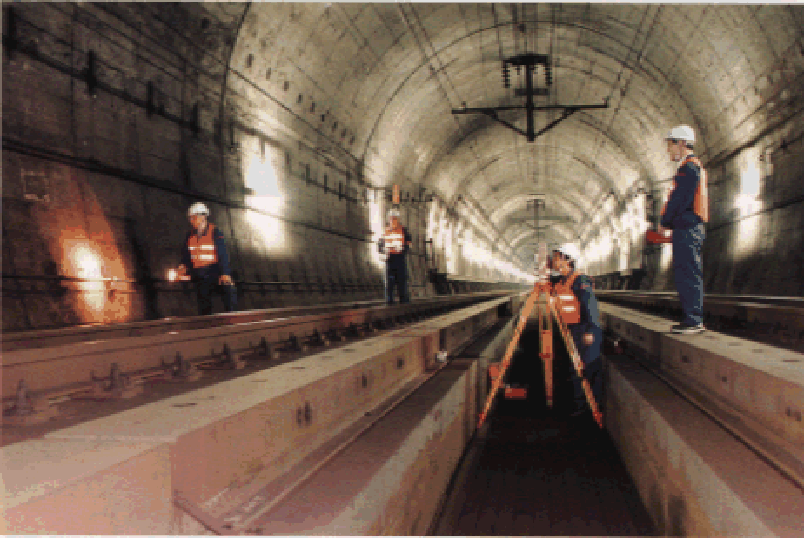
aide of measuring lines established at 77 cross sections in the main tunnel and at 67 cross sections in the pilot tunnels and maintenance shafts. Since the tunnel's opening, these measurements have been made two to three times a year by inspectors using measuring equipment during the short (approx. 10 min.) intervals when no trains pass (Photo 1 and Fig. 2). Initially, these measurements were made optically using two transits. However, as trains are running at higher speeds and with denser schedules than before, plus the factor that bullet trains are scheduled to run through the tunnel in the future, a three-dimensional instrumentation system using an electro-optical distance meter was developed and is now used for the measurements. This system shortens measuring time as well as improves safety during measurement without the risk of accidental shorting of track circuits.
In addition to the flow meters installed in drain
gutters, seepage water flowing out of tunnel walls is measured at 28 measuring
points and analyzed chemically to grasp variations in water quality. Further,
in-situ strain meters and measuring lock bolts are installed in maintenance
shafts and pilot tunnels to determine bedrock behavior. Since this tunnel exists
in conditions under which the structure is always subject to high water
pressure, various chemical analyses and tests are made on samples taken from
lining concrete, spray concrete and concrete in grouted cut-off areas to measure
the deterioration of materials.
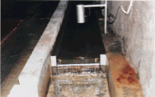
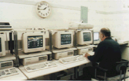
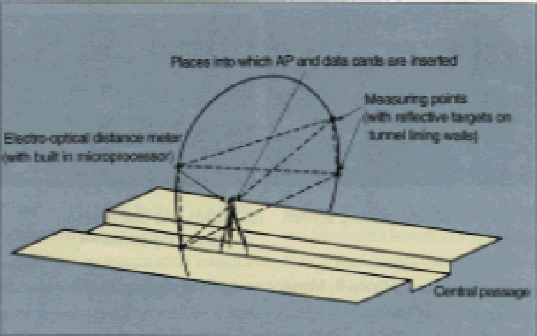
Fig. 2 Measurement of tunnel cross sectional dimensions using a three-dimensional instrumentation system
MEASUREMENTS DURING
MAINTENANCE
Measurements indicate that the tunnel is functioning
well. Some interesting facts were obtained from the measured data.
Effects of Earthquakes:
Large earthquakes have occurred four times around the tunnel during the past few years. Of the quakes, the largest earthquake ground motion, with a maximum acceleration of 56 gals, was detected during the Hokkaido Nansei Oki Earthquake of July 12, 1993. In contrast, acceleration measured on the surface, in Kikonai, was 214 gals. This proves that earthquake ground motion under the seabed was appreciably smaller than that on the surface. The results of inspections made inside the tunnel immediately after the four earthquakes showed no effect of the quakes on the tunnel structure.
Seepage Water:
By courtesy of Yoshioka Management Center, Sapporo Construction Office, Japan Railway Construction
Public Corp.
The flow rate of seepage water, a matter of primary concern with undersea tunnels, shows a trend of gradual decrease: from 32 m3/min. at the time of opening to 24 m3/min. at present, although it increased once immediately after an earthquake. It is to be noted that a decrease in flow rate is a plus in terms of a decreased need in pumping power, but will have an adverse effect on tunnel stability if this leads to an increase in water pressure at the back of the tunnel lining. Since chemical compositions in seepage water have shown little significant variation and now appear in a stable state, there seems to be no degradation of lining and grouting materials due to contact with sea water.
Strains in Lining Concrete:
Results of analyses on data about strains in lining
concrete measured by the system indicate that the strains change periodically,
showing a strong correlation between the ebb and flow of the tide on a daily
basis, the waxing and waning of the moon on a monthly basis, and the mean tide
level on a yearly basis.
Displacements of the Tunnel:
Measured displacements of the tunnel are on the
whole small with no sharp changes observed at present. The soil characteristics
and tunnel support patterns may have some bearing on displacements. The results
of analyses on measured data, such as classifying tunnel sectional deformation
patterns and pinpointing locations of large deformations, provide information
necessary to perform efficient tunnel maintenance in the future.
MAINTENANCE TECHNOLOGY
BECOMING A TOPIC OF
INTEREST
Maintenance technology for civil engineering
structures is one area of growing future interest from the viewpoint of
efficient maintenance of high quality infrastructures. Maintenance techniques
adopted for this tunnel are seen as valuable and innovative technology for
maintaining long undersea tunnels.