Nishiseto Expressway's Kurushima Bridge
THE HONSHU-SHIKOKU
BRIDGES ON ONOMICHI-
IMABARI ROUTE
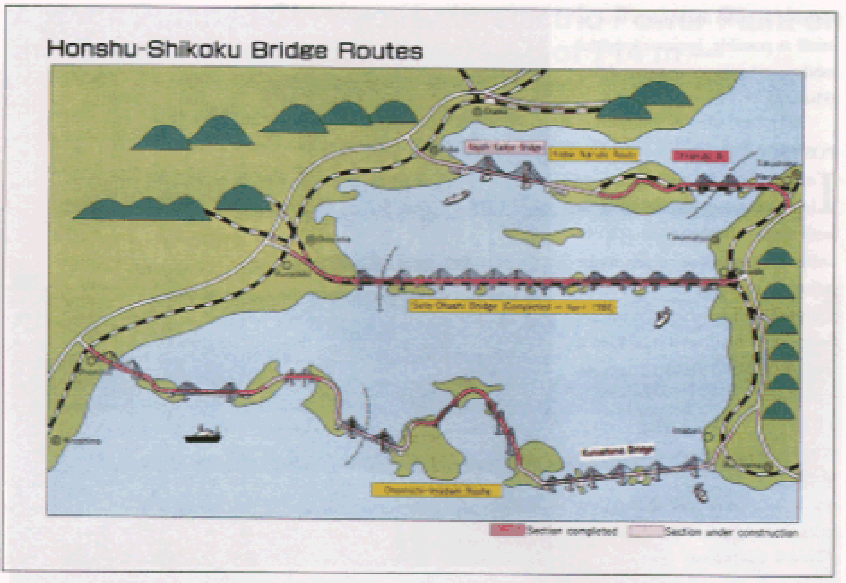
Bridges connecting Honshu and Shikoku on three separate routes, Kojima to Sakaide, Kobe to Naruto, and Onomichi to Imabari, are now under construction. The bridges will play a key role both as local links and as part of a national road network traversing the Japanese Archipelago (Fig 1).
The Nishi Seto Expressway on the Onomichi-Imabari Route is now under construction through improvement work on Route 317, a high standard arterial road, linking nine islands, including Mukaishima, Innoshima, Iguchijima, Ohmishima, Hakatashima, Ohshima, and Umashima. The road plays two roles, one as a link between Honshu and Shikoku and the other as a traffic route to the islands. Uniquely, bridges on this route will be provided with exclusive lanes for motorcycles, bicycles and pedestrians.
The expressway's total length is about 60 km, about
45% of which is now in-service. Three bridges now under construction, including
Kurushima Bridge, are scheduled to be completed in 1998.
OUTLINE OF KURUSHIMA
BRIDGE -THREE
CONTINUOUS SUSPENSION
BRIDGES
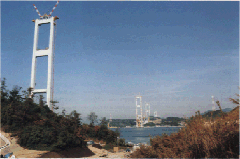
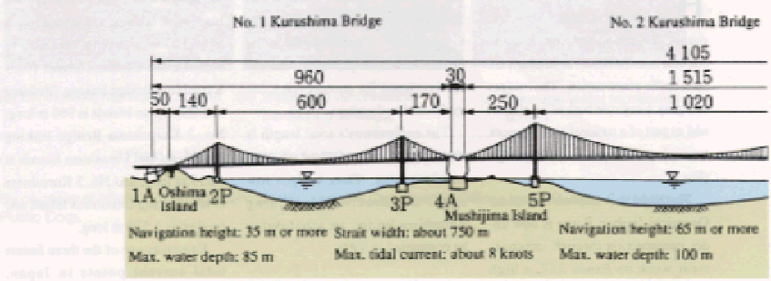
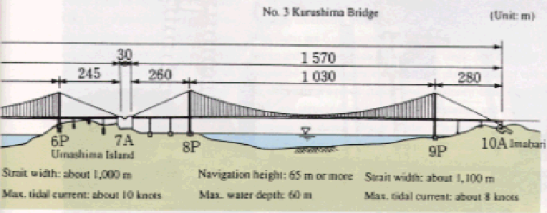
urushima Bridge is the world's first set of three back-to-back suspension bridges, with a total length of 4,105 m, linking Imabari in Shikoku and Oshima Island: No. 1 Kurushima Bridge linking Oshima and Mushijima Islands is 960 m long; No. 2 Kurushima Bridge linking Mushijima and Umashima Islands is 1,515 m long; and No. 3 Kurushima Bridge linking Umashima Island and Imabari is 1,570 m long.
Known as one of the three fastest tidal current
points in Japan, Kurushima Strait, which the bridges span, is located between
Oshima Island and Imabari, and is a scenic spot boasting a view characteristic
of the Inland Sea of Japan. The strait is approximately 4 km wide and is an
important navigation route. A strong tide runs at up to 10 knots, and about
10,000 ships pass through each day.
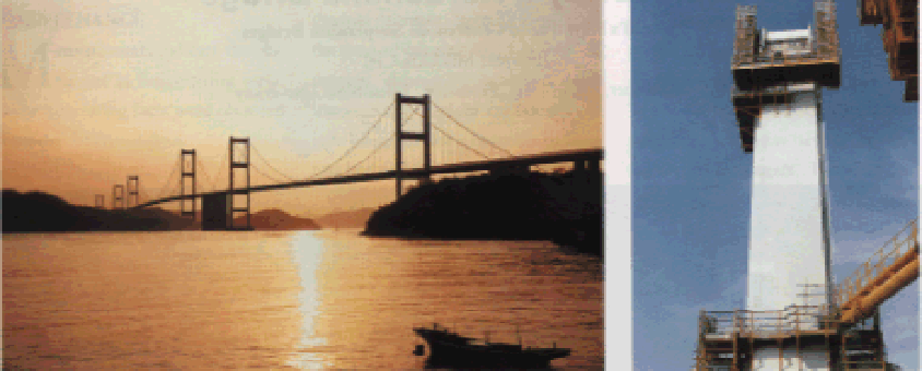
Fig. 1 Honshu-Shikoku Bridges Photo 2 Bolt
splicing joints of main tower 2P (these cannot
seen from the outside)
Since the construction site is very important in
terms of both environmental preservation and sea transportation, when deciding
the expressway route and the configuration and dimensions of main towers and
anchorages, consideration was given to making the most of existing natural
terrain, preserving landscapes and minimizing the impact on shipping lanes.
Three suspension bridges were designed to get the most out of existing site
conditions and to be economically advantageous in that two adjacent anchorages
could be made into one and the size of anchorages could be reduced.
CONSIDERATION GIVEN TO
LANDSCAPES
The sections of bridge at the scenic points were designed with consideration given to
landscapes. Box girders and crisscross sectional main towers adopted to assure stability against winds were designed to cast shadows that give an impression of sharpness and are tapered at the top to produce a sense of liveliness. Further, the main towers are of simple construction with a combination of horizontal beams. Of the six main towers, the height of the three on the Oshima island side gradually lowers as the island is approached; this is done without correspondence to the main span to create an impression of continuity (Fig. 2 and Photo 1).
By courtesy of Imabari Construction Office, Third Construction Bureau,
Honshu-Shikoku Bridges Authority
Additionally, for main towers 2P and 3P and horizontal beams connecting tower shafts that can be seen from vehicles during travel, jointing materials were used inside the shafts and beams so that splicing bolts would be invisible when viewed from the outside. This is named, instead of conventional friction type connection, tensile (bolt) type connection for the shafts, and longitudinal stiffener type connection for the beams. It not only simplifies outward appearances, but also ensures safety in field work and shortens construction periods (Photos 2 and 3).
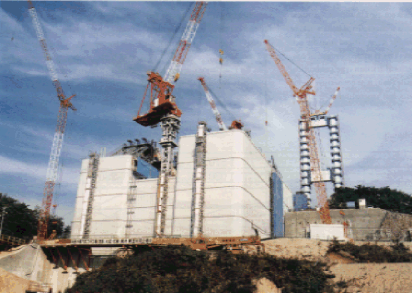
As for foundations, a pier is installed between main tower 2P and anchorage 1A to reduce anchorage size. The number of anchorages for the three continuous suspension bridges has been reduced to four. Anchorage 10A on the Imabari side is of tunnel anchor type to minimize changes to existing terrain. For exterior walls, molds for precast concrete are used, joints provided, and corners rounded to make anchorages look as small as possible, improve long-durability, and enhance maintainability (Photo 4).
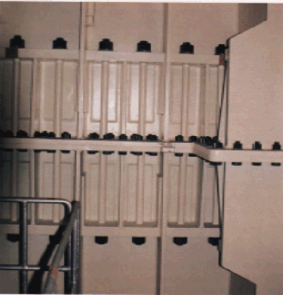
Photo 3 Bolt splicing joints of main tower 2P (viewed from the inside)
?@
POSTSCRIPT
In addition to the above characteristic features,
cylindrical caissons were adopted for the construction of undersea foundations
subject to the influence of strong tides. A barge equipped with an automatic
control system which allowed it to keep a fixed position without using mooring
ropes was developed to erect stiffening girders. As a measure against strong
winds, vibration damping devices were used in erecting main towers. Thus a great
deal of advanced technology was developed and employed in this project.